Machines
Hydraulic Ball Tube Expansion System (Polymer/Steel Ball)
Contact for quote
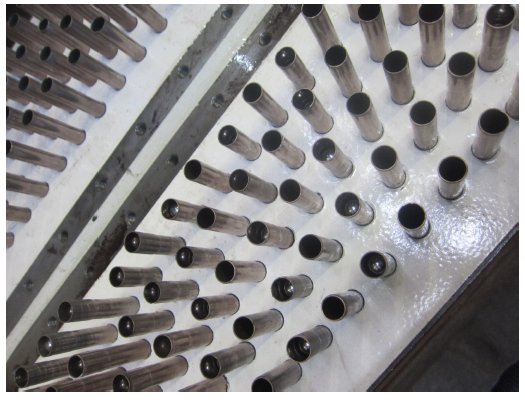
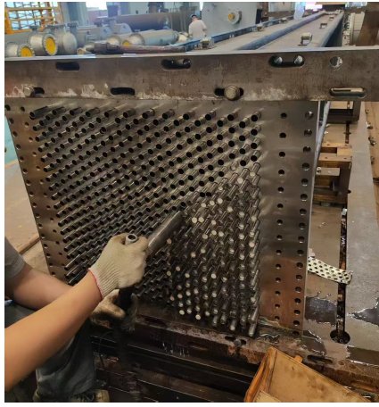
A two-stage hydraulic tube expansion system that pushes a polymer or cemented-carbide steel ball through the full tube length — a different expansion method from our rod-driven expanders.
This system expands heat-exchanger tubes against their fins by hydraulically pushing a ball — polymer or cemented-carbide steel — through the full length of the tube, rather than driving a rod through in steps. It's supplied as two linked stages: a BSB tube-end flaring system and a BE ball-expansion system.
BSB tube-end flaring: one tube-end forming tool (BS series) plus a hydraulic power unit. The tool is sized to the tube's outer diameter, maximum wall thickness and required flaring depth, and is machined from heat-treated stainless steel for long service life. In use, the tube is inserted into the flaring tool and connected to the power unit; hydraulic pressure closes the tool's clamping jaws on the tube's outer wall while an internal piston rod extends outward, pressing an expansion ball into the tube end to form a flared, bell-mouth shape — this sets the insertion dimension for the expansion stage that follows. Tube outer-diameter roundness should conform to NB/T47019.1 Clause 6.6.1, with wall-thickness tolerance of -0.05mm to 0.
BE ball expansion: BE tooling plus an HPB high-pressure ball-expansion pump unit, rated to 50 MPa maximum working pressure. After the BS tool flares the tube end and the expansion ball is placed inside, the BE tool inserts into the tube and clamps its outer wall, sealing against the tool. Water pressure is then raised continuously until there's enough hydraulic force to push the ball the full length of the tube, expanding it outward against the fins in one continuous pass.
Example tube configurations this system has been engineered for (ball material and size are matched to each tube, so treat these as representative, not a fixed spec):
— Ø15.88×0.6mm austenitic stainless steel tube, 16.4mm fin hole, expanded to 16.48–16.6mm OD (0.08–0.2mm interference fit), with a Ø15.45mm steel ball.
— Ø13.5×0.55mm 70/30 copper-nickel double-layer tube (inner tube plus a Ø15.87mm OD / 13.87mm ID outer sleeve, 1.0mm wall), 16.4mm fin hole, with a Ø13.35mm steel ball.
— Ø20×0.79mm copper-alloy tube, 20.5mm fin hole, expanded to 20.58–20.7mm OD, with a Ø19.1mm steel ball.
Before shipment, we ask for 15–20 sample tubes (1m each) plus fin samples to run pre-shipment testing on your exact material.
Request a Quote for This ItemTechnical Specifications
| Note | Example tube configurations shown — ball material/size engineered per tube |
|---|---|
| Expansion Method | Hydraulic ball push (full tube length, single pass) |
| Ball Material Options | Polymer or cemented-carbide steel |
| Max Working Pressure | 50 MPa |
| System Stages | BSB tube-end flaring + BE ball expansion (HPB pump) |
| Flaring Tool Material | Heat-treated stainless steel |
| Tube Roundness Standard | NB/T47019.1 Clause 6.6.1 |
| Wall Thickness Tolerance | -0.05mm to 0 |
| Example: Stainless Tube | Ø15.88×0.6mm, 16.4mm fin hole → Ø15.45mm ball |
| Example: Cu-Ni Tube | Ø13.5×0.55mm (double-layer), 16.4mm fin hole → Ø13.35mm ball |
| Example: Cu-Alloy Tube | Ø20×0.79mm, 20.5mm fin hole → Ø19.1mm ball |
| Pre-Shipment Testing | 15–20 sample tubes (1m) + fin samples |
More from Machines
machines
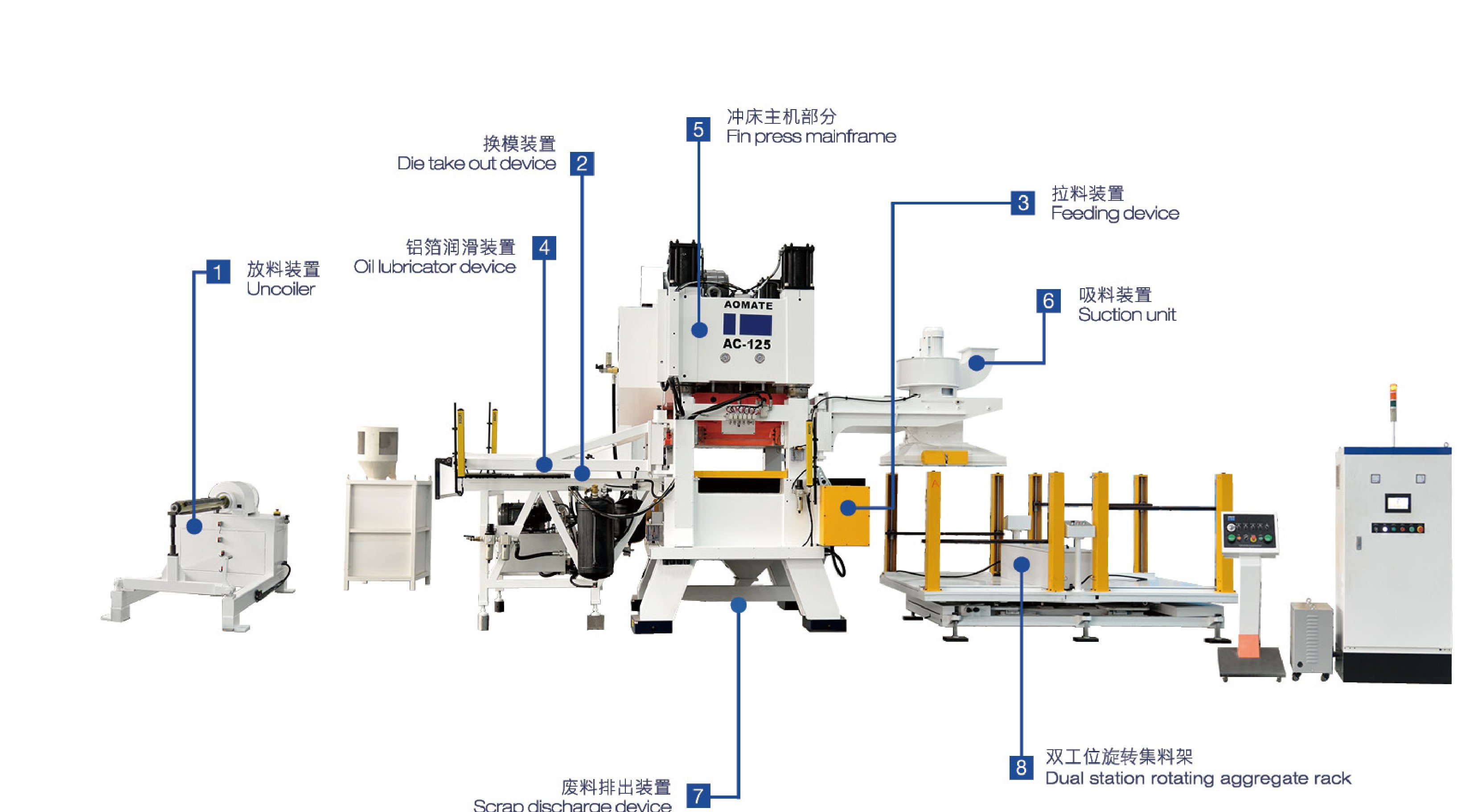
AC Series Automatic Fin Press Line (High-Speed, Parallel/Dual-Shaft)
A complete high-speed automatic fin press production line for air-conditioning/refrigeration fins, from coil uncoiler through to dual-station finished-fin collection.
machines
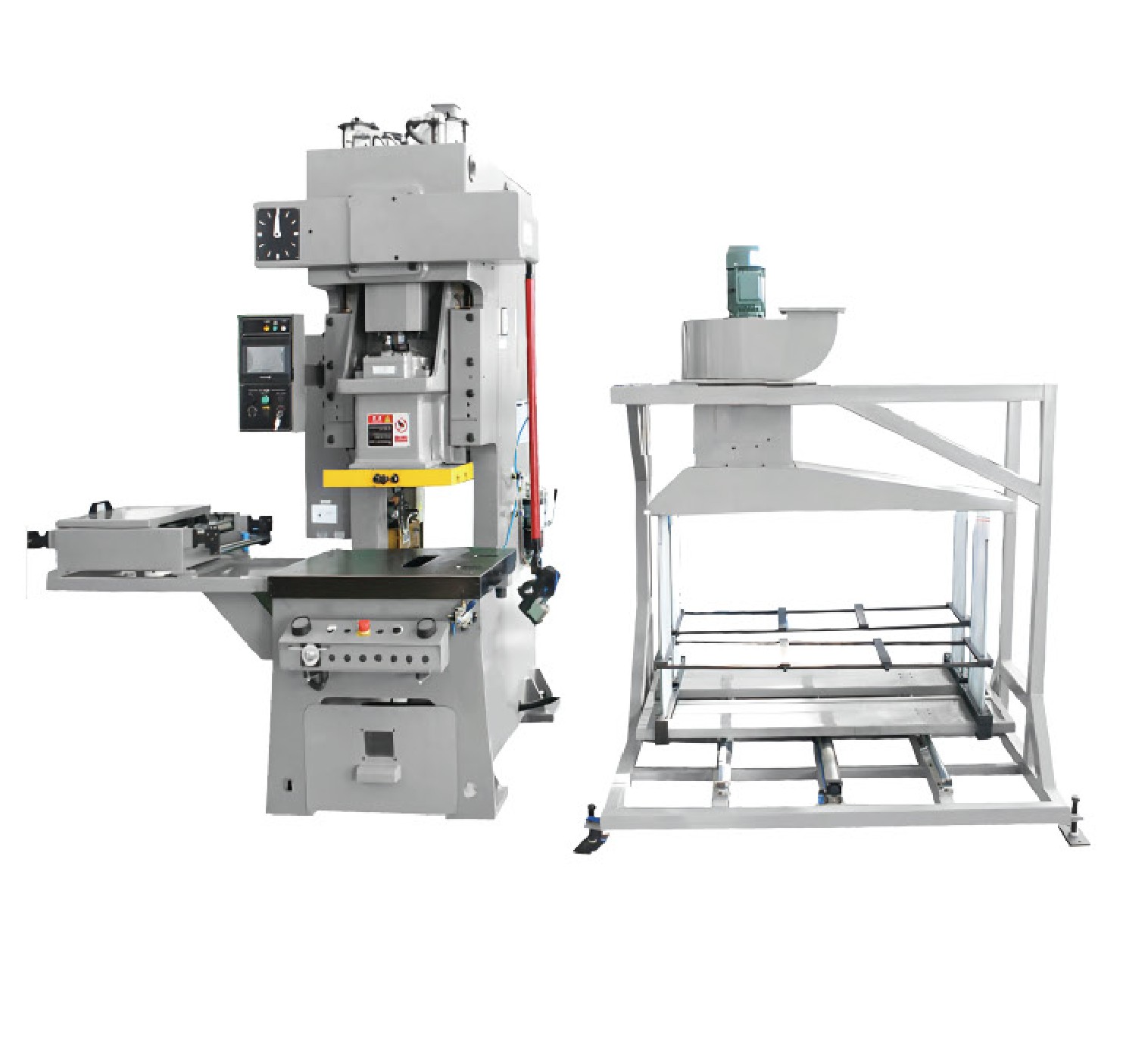
AK Series Open-Type Fin Press
An open-type high-speed precision fin press line for the refrigeration industry, with PLC and rotary-encoder control, variable-frequency drive and hydraulic overload protection.

machines
CNC Spin-Shrinking Machine for Copper & Aluminum Tube Ends
A CNC two-axis spinning machine that necks down (shrinks) the ends of copper and aluminum tubes, with automatic feeding and unloading.
Get a Quote